|
|---|

| Home |
|
|
Forum | Links |
|
Oct 16, 2006: The table below shows data comparing the AIM4160 with several antenna analyzers that are used by amateurs. (Note: The AIM4160 is the predecessor to the AIM4170 and it has the same performance up to 160MHz.) ARRL members can access the original QST articles here: The ARRL was not involved with this series of tests on the AIM4160. |
|
All data except for the AIM4160 are from the May, '05 and Nov, '06 issues of QST. |
||||||||
| Load (Ohms) |
Freq (MHz) |
AIM4160 | Autek VA1 | Kuranishi BR-210 |
MFJ-269 | Palstar ZM-30 |
AEA Via Analyzer |
Timewave TZ-900 |
|---|---|---|---|---|---|---|---|---|
| 50 | 3.5 14 28 50 144 432 |
50 + j0 49 + j0 50 + j0 49 + j0 49 - j0 -- |
52 - j1 51 - j1 58 - j3 -- -- -- |
51 51 50 50 50 -- |
48 ± j0 48 ± j0 48 ± j0 48 ± j0 48 ± j1 1.1:1 swr |
53 + j0 52 + j0 53 + j0 -- -- -- |
50 + j0 50 + j0 50 + j0 50 + j0 |
48 + j0 48 + j0 48 + j0 48 + j0 |
| 5.0 | 3.5 14 28 50 |
5 + j0 5 + j0 5 + j0 5 + j0 |
5 - j1 6 + j0 5 - j2 -- |
<12.5 <12.5 <12.5 <12.5 |
4 ± j2 5 ± j0 4 ± j3 4 ± j5 |
3 + j2 3 + j2 3 - j4 -- |
3.2 - j0 4.1 - j0 5.5 + j2.1 5.6 + j7.9 |
2.4 + j0 2.5 + j0 2.3 + j2.6 2.6 + j3.0 |
| 25 | 3.5 14 28 50 |
25 + j0 25 + j0 25 + j0 25 + j1 |
25 - j1 25 - j0 23 + j0 -- |
26 27 27 27 |
23 ± j5 24 ± j2 23 ± j5 24 ± j6 |
24 + j0 24 + j0 25 + j0 -- |
25 + j0 25 + j0 25 + j0 25 - j6.7 |
23 + j0 24 + j0 24 + j0 24 + j0 |
| 100 | 3.5 14 28 50 |
100 + j0 100 + j0 100 + j1 100 - j0 |
100 - j0 97 + j5 84 + j0 -- |
100 100 100 100 |
99 ± j17 97 ± j10 95 ± j23 87 ± j32 |
108 + j0 106 + j0 102 + j0 -- |
102 +j0 101 + j0 99 + j0 94 - j11 |
100 + j0 101 + j0 99 + j0 97 + j0 |
| Load (Ohms) |
Freq (MHz) |
AIM4160 | Autek VA1 | Kuranishi BR-210 |
MFJ-269 | Palstar ZM-30 |
AEA Via Analyzer |
Timewave TZ-900 |
| 200 | 3.5 14 28 50 |
200 + j0 200 + j0 200 + j0 200 - j0 |
195 - j16 170 - j1 147 - j3 -- |
200 200 190 190 |
185 ± j68 183 ± j0 156 ± j86 115 ± j98 |
210 + j0 205 + j0 173 + j56 -- |
199 - j0 193 - j0 176 - j44 141 - j69 |
200 + j0 193 - j26 175 - j63 130 - j144 |
| 1000 | 3.5 14 28 50 |
989 - j12 990 - j28 998 - j61 |
900 - j46 590 - j380 420 - j11 -- |
>400 >400 >400 >400 |
661 ± j743 555 ± j368 130 ± j409 56 ± j258 |
>600 >600 104 - j449 -- |
940 + j0 419 - j510 259 - j429 131 - j238 |
979 + j0 813 - j506 607 - j534 171 - j633 |
| 50 - j50 Zmag=70.7 |
3.5 14 28 |
50 - j50 49 - j51 50 - j48 |
50 - j47 39 - j41 55 - j27 |
80 85 80 |
46 ± j47 63 ± j53 43 ± j45 |
49 - j47 44 - j50 43 - j43 |
51 - j44 47 - j47 50 - j63 |
60 - j46 71 - j48 55 - j44 |
| 50 + j50 Zmag=70.7 |
3.5 14 28 |
51 + j50 51 + j48 50 + j49 |
54 + j55 53 + j54 52 + j34 |
80 80 80 |
50 ± j51 60 ± j42 54 ± j50 |
55 + j50 60 - j51 * 67 + j53 |
55 + j50 61 + j50 58 + j55 |
65 + j51 59 + j54 70 + j51 |
| Manufacturer's suggested list price ($US) |
495 | 200 | 430 | 360 | 350 | 690 | 1300 | |
| * The 14MHz data in the original QST review is: 60 - j51. The sign is shown correctly for 3.5 and 28MHz. | ||||||||
|
Load Component Values |
||
|---|---|---|
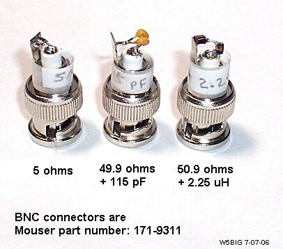
The tests designed by the ARRL use three types of loads:
The AIM4160 was calibrated using the normal cal procedure: a short circuit, an open circuit and a 49.9 ohm chip resistor. The same calibration data was used for all the tests. The test loads connected to the AIM4160 were made using standard components from Mouser and Digikey. The components were used directly from the package. The loads were not adjusted using laboratory equipment. |
||
|
The following table shows the construction details of the loads used for this series of tests.
The ideal value of each load is shown in the first column of the table below. The expected value of impedance based on the component values specified in the catalog is shown in italics below the ideal value. All the resistor are surface mount size 0805 1% metal film. |
||
| Load | Part Number | Comments |
| 5 ohm | Digikey RHM10.0CCT 1% metal film | two 10 ohm resistors in parallel |
| 25 ohm | Digikey RHM49.9CCT | two 49.9 ohm resistors in parallel |
| 50 ohm | Digikey RHM49.9CCT | |
| 100 ohm | Digikey RHM100CCT | |
| 200 ohm | Digikey RHM200CCT | |
| 1K ohm | Digikey RHM1.00KCCT | |
| 50 - j50 @ 3.5MHz (ideal=49.9 - j49.4) |
49.9 ohms 1% Digikey RHM49.9CCT + |
Capacitors are 100V COG with leads. Two caps in parallel = 920pF. |
| 50 - j50 @ 14MHz (ideal=49.9 - j51.7) |
49.9 ohms 1% Digikey RHM49.9CCT + |
Capacitors are 100V COG with leads. Two caps in parallel = 220pF. |
| 50 - j50 @ 28MHz (ideal=49.9 - j49.4) |
49.9 ohms 1% Digikey RHM49.9CCT + |
Capacitors are 100V COG with leads. Two caps in parallel = 115pF. |
| For the 50 + j50 loads, the resistive component is the sum of a fixed resistance and the specified coil resistance. For all three loads shown below, the fixed resistance is 48.7 ohms. The specified resistance of the coil is added to this to get the ideal value. | ||
| 50 + j50 @ 3.5MHz (ideal=50.9 + j49.4) |
Coil series resistance = 2.2 ohms. Total resistance = 50.9 ohms Total inductance = 2.25uH |
|
| 50 + j50 @ 14MHz (ideal=50.0 + j50.6) |
Coil series resistance = 1.3 ohms. Total resistance = 50.0 ohms Total inductance = 575nH |
|
| 50 + j50 @ 28MHz (ideal=49.6 + j50.1) |
Coil series resistance = 0.9 ohms. Total resistance = 49.6 ohms Total inductance = 285nH |
|
|
||
