|
|---|
| Home |
|
|
|
FAQ | Forum | Links |
|
March 30, 2018
An example was found recently in Europe where an AIM that had been in used for a long time appeared to stop working abruptly. A new AIM was purchased and it would not work at all. After much testing the problem was found to be a power supply (wall wart) that was not isolated and the resulting ground loop keep the AIM's from working. Fortunately they were not damaged. After a wall wart with an isolation transformer was used, the AIM's worked ok. This shows a subtle problem that can result when the hot and ground wires of a two wire distribution system are reversed. This can sometimes result in damage to the equipment and even personal injury. If you have any doubt about your power supply, the AIM can be operated with a conventional 9V battery for several hours. For the first basic test, the cable to the PC does not have to be connected. The AIM will come on with the Green LED glowing normally. Note that the average DC output of the power supply may be within spec but there may be droop. If the voltage droops below about 5V during a scan, the data will be very noisy. The DC input is checked at the end of each scan to try to catch excessive droop. If the AIM works with the 9V battery (or a known good lab power supply) but not with your wall wart, check the output of the wall wart with a scope while the scan is in progress. The following article shows some of the pitfalls due to the AC power distribution system. Be careful! In areas where the AC power is distributed by only two wires, the phase of the connections has to be carefully observed. One wire is called Hot and the other is Ground. For an example, I will use the two-wire distribution method commonly found in the Philippines. One wire is the physical ground and the other is nominally 240VAC although it may be as low as 200VAC at the wall socket. The frequency is 60 Hz. The wiring of sockets is not consistent and it is essential to check to see which terminal of a socket is hot and which is ground. This can be done using a simple neon bulb test device. These are advertised on-line for two or three dollars. I haven't evaluated either of these devices but this does show that useful tools should be available for only a few dollars. 
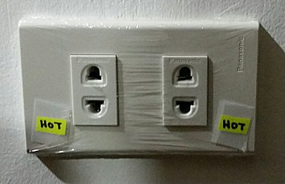
After checking a couple of hardware stores, I could not find one on the shelf so I made one using parts I had on hand. Put a label on the hot side of each socket. Below are two sockets I found in the same room.
Socket Number 1 is polarized like sockets in the US with slots of different widths. The narrow slot should be hot. In this case, the hot wire was connected to the correct terminal. That may not always be the case. The cable shown connected to Socket Number 1 above goes to a microwave oven that has a plain (unpolarized) two prong male plug. The cabinet of the microwave is hot when the cable is not connected properly. (The microwave works ok in either case.) If there is another electrical device or water pipe nearby, this could be a shock hazard. The microwave itself comes with a wire attached to the back of the cabinet for an external ground but there is no ground connection available at the power socket. Socket Number 2 has the hot wire incorrectly connected to the wider slot. There is a real hazard if different equipment is plugged into these sockets. If these pieces of equipment have different grounds, they may be damaged when a cable is connected between them. Plug strips used for expanding the power socket are potential hazards too.
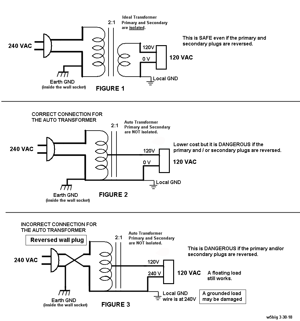
Labels on the connectors and the cables are necessary to make sure the phasing is correct. If your main AC supply is 240VAC and you have equipment that requires 120VAC, then a 2:1 transformer is needed. I bought two transformers from different companies but both of them are AUTO transformers which do not isolate the primary and seconday. The auto transformer is less expensive and it can be used for the majority of household applications, so the local stores in my area only stock this type of transformer. One terminal is common between the input and output. This common terminal was not indicated on the label of the transformer. I had to determine it using an ohmmeter. In this case it is very important to label the transformer primary and secondary and make sure the primary is always properly connected to the wall socket. If the power connections are accidentally exchanged when rearranging equipment, it can lead to a disaster. Note the transformer secondary is not polarized and a two prong plug can still be inserted in with either orientation.
TRANSFORMER CIRCUITS
The following page has a lot of general information about power distribution. |


